

Transmission Control Unit Circuit Board Schematic Reverse Engineering
Reverse engineering the circuit board of a Transmission Control Unit (TCU) is a complex yet crucial task in various industries, including automotive, aerospace, and industrial applications. The goal of reverse engineering is to replicate or duplicate the original electronic circuit, enabling manufacturers to restore a malfunctioning TCU or create a prototype for further development. In this article, we will explore the key steps involved in reverse engineering a TCU circuit board schematic, including the use of schematic diagrams, layout drawings, BOM lists, and more.
The Process of Reverse Engineering a TCU Circuit Board
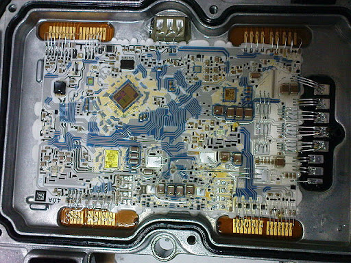
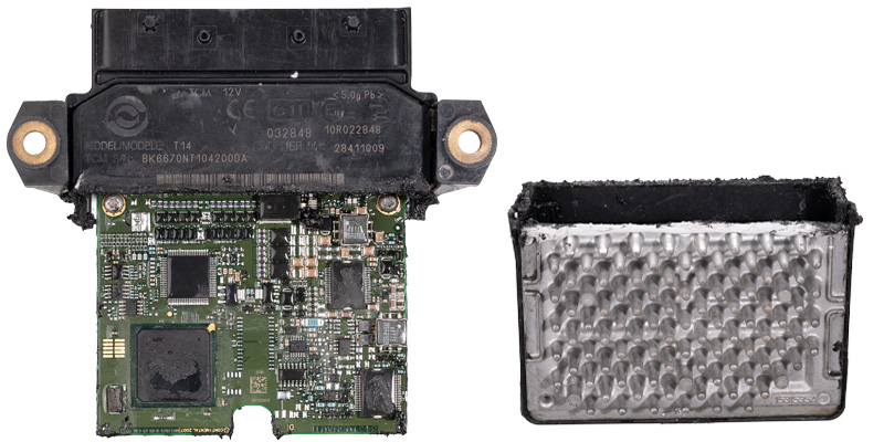
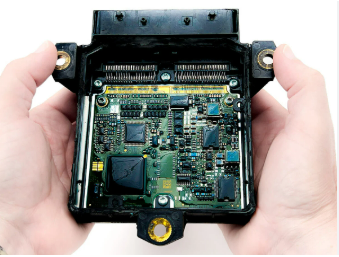
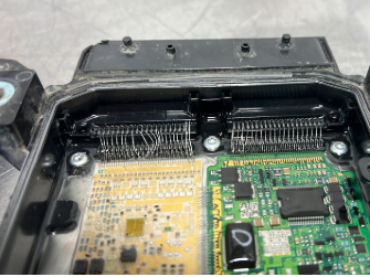
Initial Assessment: The first step in reverse engineering a TCU circuit board is to thoroughly examine the existing PCB board. This involves identifying all components and understanding the general functionality of the electronic circuit board. Often, the netlist and CAD file of the original design are unavailable, which means the process relies heavily on visual inspection and testing.
Schematic Diagram Creation: Once the physical board is examined, the next step is to reproduce the schematic diagram. This involves mapping the electrical connections and component
placements onto a digital platform. Using specialized software tools, engineers can modify or clone the circuit design, often creating a new layout drawing that mirrors the original TCU’s design.
Bill of Materials (BOM) and Netlist Generation: After the schematic is created, engineers generate a BOM list, which includes all the components used in the TCU circuit. Additionally, a netlist is developed, which represents the electrical connections between the components. These documents are critical for the remanufacture or recovery of the circuit board, ensuring that all components are correctly sourced and placed.
Gerber File and Pick & Place Data: With the schematic, BOM list, and netlist in hand, engineers create Gerber files. These files contain detailed information for the PCB manufacturing process, including component layout and routing details. Pick & place data is also generated to guide automated assembly machines in correctly placing components on the PCB.
Prototype and Testing: After the schematic and manufacturing data are prepared, a prototype of the TCU circuit board is produced. This prototype undergoes extensive testing to ensure that it functions as expected, replicating the performance of the original design. If necessary, modifications can be made to improve functionality or address any identified issues.
Applications of TCU Reverse Engineering
Reverse engineering a Transmission Control Unit circuit board is particularly valuable in industries where original parts are no longer available or need to be recovered due to damage or obsolescence. It can also be used to clone designs for research and development, improve efficiency, or introduce upgrades to legacy systems.
In conclusion, reverse engineering a TCU circuit board schematic involves a meticulous process of replicating, restoring, and reproducing complex designs. The ability to generate accurate schematic diagrams, layout drawings, and Gerber files is essential for the successful remanufacture of these critical components.