Reverse Engineering PCB Display Adjustment
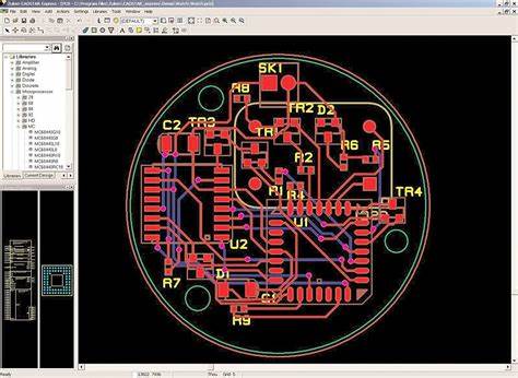
Reverse Engineering PCB Display Adjustment is a necessary step to take when draw the Printed circuit board layout according to the scanned images over the physical boards, proper adjustment over the display image can greatly ensure the accuracy of PCB schematic diagram and layout drawing and increase the processing speed;

Procedure of Display Adjustment for Reverse Engineering PCB
· Reconnect cable and probe. The screen should look similar to the left side box of Figure 25.
Select the horizontal positioning arrow (⇔) located at the top left of the touch screen.
– Use both upper and lower knobs located on the front panel to adjust time per division and horizontal position so the displayed response is similar to the right side box of Figure 25. Set time/div to ~ 1ns/div to ensure PCB clone accuracy.
Select the vertical scaling positioning arrows located at the middle left side of the touch screen.
– Use both the upper and lower knobs located on the front panel to adjust rho/div and vertical position as illustrated in Figure 26. Set rho/div to 60 mrho/div.
Probe the test coupon and continue adjusting both the horizontal and vertical scaling until the launch edge is aligned with the first division and the reflected edge is aligned with the last. The vertical scaling should be adjusted to ~60mrho to maximize the reflection (~50%) on the screen. Horizontal scaling will be dependent upon coupon length. The screen should look similar to Figure 27 under probing conditions in the process of PCB Clone service.
Procedure
- · Probe coupon, allow for settling time, push RUN/STOP to stop acquisition.
- · Push Measurement Button
Select mean(touch screen)
Select exit(touch screen)
Select the measure box located in the lower left of the touch screen and a menu should appear on the screen.
– Set the left and right limits to 50 and 70% respectively using the upper and lower knobs located on the front panel or the numeric, touch screen pad. The rho measurement will be the mean value between the two limits and can be used to determine mean impedance. The Tektronix units for rho are displayed in mili-rho(mrho) where: rho = 0.001*mrho Zload = 50*((1+rho)/(1-rho))
Tags: reverse engineering circuit board,reverse engineering circuit card,reverse engineering pcb,reverse engineering pcb assemble,reverse engineering pcb board,reverse engineering pcb card,reverse engineering pcba,reverse engineering printed circuit board,reverse engineering printed wiring board,reverse engineering pwb,reverse engineering pwba

