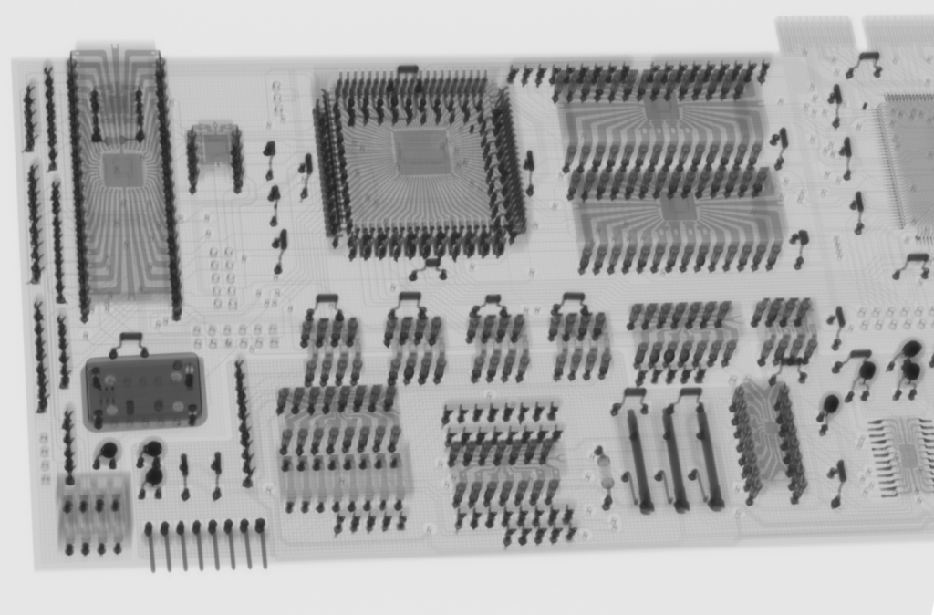
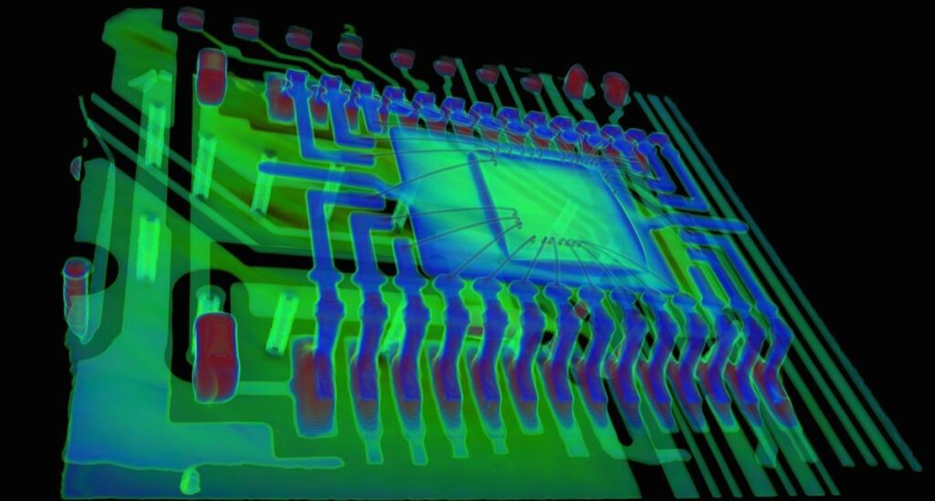
Reverse Engineering Computed Tomography PCB Board
Organization is the key to reverse engineering computed tomography PCB board efficiency, and lack of organization will reduce the efficiency of our PCB design reverse engineering. Take printed circuit board gerber file relayouting rules as an example: when starting a new project, many PCB design engineers tend to reinvent the design according to their own design rules, rather than relying on a proper, organized, systematic approach to rules.

This practice can significantly slow down project progress when time is of the essence. This article will discuss rule-based approaches that can improve the efficiency of multilayer Computed Tomography circuit board schematic diagram reverse engineering.
It is common practice to recreate PCB design rules for each new project underway. This may be because the design department does not yet have a process in place to reuse the rules, or simply because the PCB design engineer does not want to reuse the rules.

Whatever the reason, this points to the need to update design workflows to improve design efficiency and consistency. Without improvements and enhancements, current workflows can take a lot of extra time and effort, and inconsistencies can lead to inheritance issues.
The design cloning rules for each Computed Tomography multilayer circuit board are different. Generally, we expect PCB design engineers to fully understand the rules and be able to enter the same values in every design. However, even if their memory is correct, there is always the possibility of entering wrong values.


