Reverse Engineer PCB Board PWM Circuit
Reverse Engineer PCB Board PWM Circuit is similar to arranging other types of power circuits on a printed circuit board; the load device should be placed close to the PWM output to minimize impedance.

Layout planning ahead of time is essential to make full use of cooling fans and ensure that larger components do not block the air flow to the controller or other low-profile components.
You should also ensure that the PWM circuit is isolated from other sensitive circuits when relayout electronic pcb board diagram, and try to avoid wiring other circuits under the PWM circuit.

It is also a good way to use the internal ground plane as a shield for other signal layers.
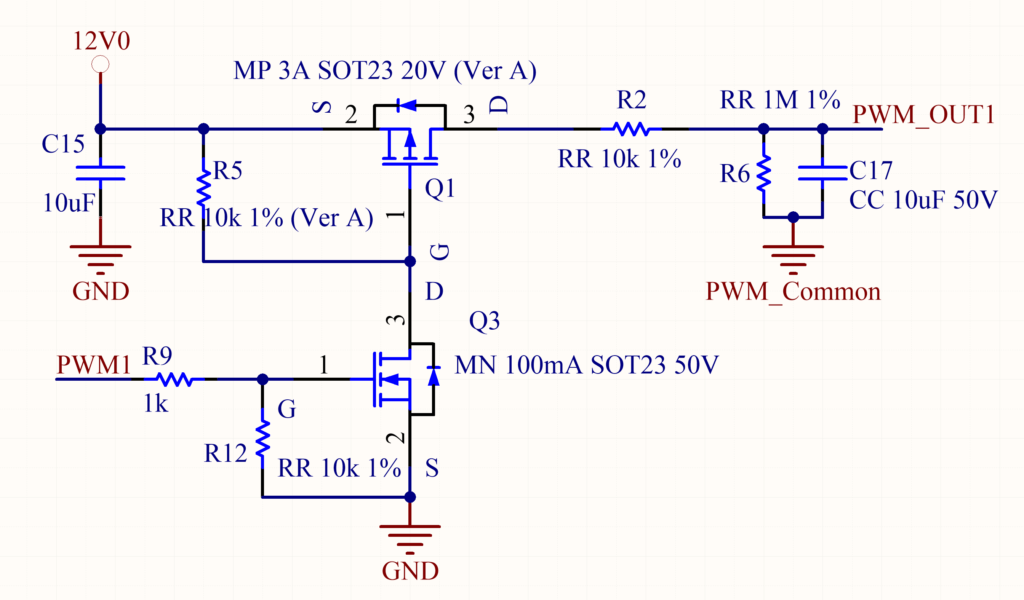
PWM is a very effective method of digitally controlling power. Although many PWM circuits are built using different timing chips, there are also PWM outputs in microprocessor chips.
The PWM function built into the computer CPU is very useful in controlling variable speed fan motors or LEDs. For example, for LEDs, when current is applied to them, they are non-linear, and only 50% of the current will not produce 50% of the light. This makes the LED difficult to control by changing the current, and the use of PWM can be more linear control of the light level.

