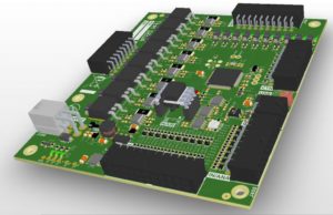
Replicating PCB Card Layout
In the process of replicating pcb card Layout, Run PCB on the new layout by running ‘pcb preamp.pcb’. Load the netlist file by selecting “load netlist file” from the “file” menu. In the file selection dialog box, choose ‘preamp.net’.
This loads connectivity information into PCB. Using the selection tool, grab and move apart the various footprints with the middle mouse button.
Once the parts are moved apart from each other, choose “optimize ratsnest” from the “Connects” menu. This menu choice will display and optimize the rats nest. Use the rats nest to help guide placement of the parts from replicating pcb card Layout.
You may wish to re-run the “optimize rats-nest” command after moving parts around. After the placement is complete, use the line tool to add traces to the board. As traces are added, the corresponding rats line will disappear.
If schematic changes are made after the layout has started, gsch2pcb can be used to forward annotate these changes to the layout. To forward annotate schematic changes, run ‘gsch2pcb project’ before replicating pcb card Layout.
This command will create the files ‘preamp.new.pcb’, ‘preamp.net’, and modify the file ‘preamp.pcb’. The modifications to ‘preamp.pcb’ include forward annotation of schematic component value changes, adds any new components, and removes any deleted components.
9.2.1 Generate Photoplot Files (RS-274-X) After the layout is complete, choose “edit layer-groupings” from the “Settings” menu. The LayerGroups form lets you specify which layers will appear in each output layer group.
For example, in the default form, layer group 1 has “front” and “front side” in it. The output file ‘1.gbr’ if DOS file names are used, or ‘somename_front.gbr’ if long file names are used will contain the “front” and “front side” layers in it. Usually the defaults are sufficient, but this form is still a useful reference.
Choose “print layout…” from the “File” menu. In the print dialog box, select “Gerber/RS-274X” for the device driver. Select the “outline”, “alignment”, and “drillhelper” options if replicating pcb card Layout.
To get DOS compatible file names, select the “DOS (8.3) names” option, otherwise enter “preamp” for the filename. Press “OK”. The following output files should have been created in the project directory. The names in parentheses correspond to the DOS compatible output file names when REVERSE ENGINEERING PCB.


