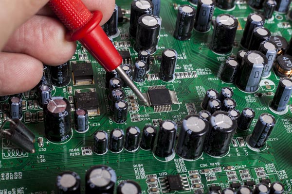
Record Keeping when Disassembly a PCB
Disassembly a PCB is an critical process when reverse engineering PCB, in order to have the bare PCB board which can scan the TOP & BOTTOM side of PCB board, all the components assemblied on it must be removed properly and clearly. When disassembling the Printed Circuit Board, notes should be recorded for possible assembly procedures to be included in the technical data package which include Layout drawing, Gerber file, BOM and schematic diagram.

For example, when disassemble the electrical wire from connector mounted on the Pwb, the sequence and corresponding color of each wire should be recorded individually. Photos must be taken before any movement. As they are disassembled, a list of all piece-parts/components should be created, including quantities and special part markings which may indicate that the part is either commercially available or a military specifications part. A layout of the parts, marked with the assembly sequence, may be useful for creating the assembly drawing and for reassembly of the item.
Tags: reverse engineering pcb circuit design,reverse engineering pcb circuit diagram,reverse engineering pcb circuit schematic,reverse engineering pcb layout,reverse engineering pcb schematic diagram,reverse engineering pcb wiring diagram,reverse engineering pcb wiring schematic

