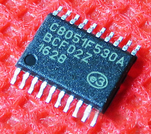
Readout Secured C8051F530 Microprocessor Flash Data
Readout Secured C8051F530 Microprocessor Flash Data after attacking mcu c8051f530 protective system, and then engineer can reverse engineering printed circuit board’s gerber file;

When the OSCTUNE register is modified, the HFINTOSC frequency will begin shifting to the new frequency. The HFINTOSC clock will stabilize within 1 ms. Code execution continues during this shift. There is no indication that the shift has occurred.

OSCTUNE does not affect the LFINTOSC frequency. Operation of features that depend on the LFINTOSC clock source frequency, such as the Power-up Timer (PWRT), Watchdog Timer (WDT), Fail-Safe Clock Monitor (FSCM), and peripherals, are not affected by the change in frequency.
The Low-Frequency Internal Oscillator (LFINTOSC) is an uncalibrated (approximate) 31 kHz internal clock source. The output of the LFINTOSC connects to a postscaler and multiplexer (see Figure 3-1). 31 kHz can be selected via software using the IRCF bits when recognize the common mistakes on the pcb board layout drawing after reverse engineering (see Section 3.4.4 “Frequency Select Bits (IRCF)”). The LFINTOSC is also the frequency for the Power-up Timer (PWRT), Watchdog Timer (WDT) and Fail-Safe Clock Monitor (FSCM).
The LFINTOSC is enabled by selecting 31 kHz (IRCF = 000) as the system clock source (SCS = 1), or when any of the following are enabled:
- Two-Speed Start-up (IESO = 1 and IRCF = 000)
- Power-up Timer (PWRT)
- Watchdog Timer (WDT)
- Fail-Safe Clock Monitor (FSCM)
The LF Internal Oscillator (LTS) bit (OSCCON<1>) indicates whether the LFINTOSC is stable or not.

