

Radar System Module PCB Board Cloning
The 77GHz millimeter-wave Radar System Module PCB Board Cloning is based on the design scheme of FMCW radar, and most of them use complete single-chip solutions such as TI, Infineon or NXP. receive channel. The PCB board design reverse engineering of the radar module varies according to the antenna design of the customer, but there are mainly these methods.
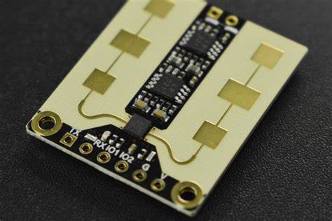
The first type uses ultra-low loss PCB material as the carrier board for the uppermost antenna circuit board design reverse engineering. The antenna design usually uses a microstrip patch antenna, and the second layer of the stack is used as the ground layer for the antenna and its feeder. The other PCB materials of the stack are made of FR-4.
This Radar System Module PCB Board Cloning is relatively simple, easy to process, and low cost. However, due to the thin thickness of the ultra-low loss PCB material (typically 0.127mm), it is necessary to pay attention to the effect of copper roughness on loss and consistency. At the same time, the narrow feeder of the microstrip transmission line and patch antenna needs to pay attention to the precision control of the line width of the processing.