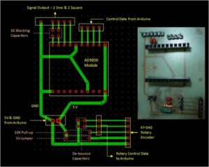
PCB Wiring Card Copying Signals
Considering the best way to implement the PCB Wiring Card Copying features impedance is monitor the what can be seen from signal transmission line. Let’s assume that transmission line as micro-strip type, and signal transmitted alongside the line can be kept in the same area.
Add the bumping signal as 1V as the fluctuation on the transmission line, bumping signal is a 1V battery, and input from head termination, and connect between the signal line and revert route. In the transient moment of battery connecting, signal voltage waveform can move in the optical speed among electrical media, and the speed is 6 inch per nanosecond; the definition of PCB Board Copying is the voltage difference between the signal lines and revert line, and it can always be measured and obtained from any point on the transmitting line which connect the signal point and reverting point.
In the process of PCB reverse engineering, signal transmit alongside the track in the speed of six inches per nano-second, in the first 10PS, signal transmit 0.06 inch alongside the track direction, presume the moment will be locked in this period of time to consider the situation of transmission line. After signal has been transmitted along this distance for a while, A stable 1V constant signal has been established among the transmitting line and corresponding revert route;
Which means a stable voltage has been made through an extra positive electric charge and extra negative electrical charge alongside this part of transmission line and its related revert route. And this stable 1V voltage signal has been generated and maintained among these two electrical conductors by the difference of these electrical charges, and the stable voltage signal among the conductors has generated a capacitor among them.
Tags: copy pcb wiring card artwork,copy pcb wiring card bill of material,copy pcb wiring card bom,copy pcb wiring card component list,copy pcb wiring card data,copy pcb wiring card design,copy pcb wiring card documents,copy pcb wiring card gerber file,copy pcb wiring card layout,copy pcb wiring card part list


