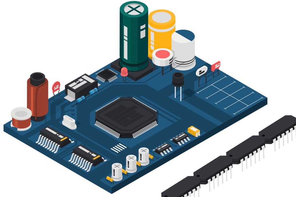
PCB Reverse Engineering by OrCAD Software
PCB Reverse Engineering by OrCAD Software start from the first step is to open your OrCAD capture program. Go to the File →New → Project. When the popup box is given choose your location to save your files, specify a unique name, and create the project using the Schematic option.

A black schematic screen is now opened so that you are ready to start creating your schematic. (note: it is assumed that the student is familiar with using the PSPICE program). Before we begin with the actual design for Cloning printed circuit board, it is a good idea to set up your libraries.
This is important for the following two reasons. First it is convenient to have a single list of components so that you do not have to search through multiple libraries every time a new part is needed when PCB Reverse Engineering, and the second reason is that certain components are not found in the given libraries and the schematic symbol will have to be made in the process of Printed circuit board Reverse Engineering. First, I will teach you how to make a simple schematic symbol.
Specify the name and pin number according to the component’s data sheet. Follow these steps for each appropriate pin. When you are finished click on rectangle tool; shown as the forth icon from the bottom on the toolbar above. Now drag a rectangle in accordance with the dotted line shown as the components perimeter after Reverse Engineering PCB process variation.
Follow these steps for each component needed to be made in your schematic. If you need components that already exist such as a resistor you simply click on the component →press CTRL + c (to copy) → click on your library and press CTRL + v to paste the component in your library. Often the component will give you extra parameters (shown as a Schmitt trigger symbol in the AND gate); these can be deleted to make your library nice and neat.
Now that you are done with your library it is time to start making your schematic. Route the schematic according to your design exactly as if you are using Capture for a PSPICE simulation. Instead of using the zero ground, it is safe to use any ground that you choose. Note in the figure below that I have route power in a similar fashion as ground using the VCC_Bar power connector, and labeling it accordingly. This is an important step to follow which will make much easier as you will see later.
Tags: duplicar pcb bom,duplicar pcb component list,duplicar pcb diagram,duplicar pcb gerber,duplicar pcb layout,duplicar pcb schematic,pcb board reverse engineering,pcb card reverse engineering,pcb reverse engineering,pcba reverse engineering,Printed Circuit Board Reverse Engineering,printed wiring board reverse engineering,pwb reverse engineering,pwba reverse engineering

