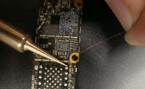
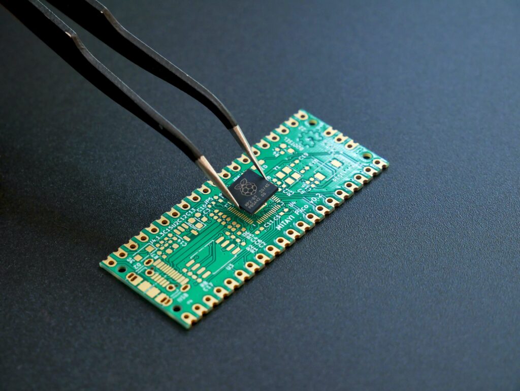
PCB Card Reverse Engineering
PCB Card Reverse engineering for switch power supply can be the final step for the whole project, if inappropriate PCB card has been reverse engineered, it will be extra electro-magnetic interference being generated which cause the un-stability of power supply operation, hereby we will list some items need to pay attention when reverse engineering PCB card:
1 From PCB card reverse engineering to Schematic diagram and Layout drawing process

Establish component parameter->input the schematic net-list->layout PCB card manually->validate reverse engineering-re-evaluation->CAM output;
2 Parameter Configuration

Adjacent track distance must satisfy the electrical security expectation, and for the convenience of operation and production, the distance among them must be as wide as it can. The minimize distance should at least undertake proper voltage from PCB card externally. When there is low density among tracks, the distance between the signal tracks can be widen, for those tracks on the PCB card with great difference of electrical level, the signal tracks should be as short as possible and widen their space, normally can layout the space at 8mil.

The hole rim of PAD to the edge of PCB Card should above 1mm which can avoid the soldering PAD damage when assemble PCB card. When the track which connect the soldering PAD is very thin, the shape of track connection point with soldering PAD should be reverse engineeried as water drop, it can not only prevent the tilt up of PAD but also makes the connection not easy to break;
Tags: pcb assemble reverse engineering,pcb board reverse engineering,pcb card reverse engineering,pcb reverse engineering,pcba reverse engineering,Printed Circuit Board Reverse Engineering,printed wiring board reverse engineering,pwb reverse engineering,pwba reverse engineering

