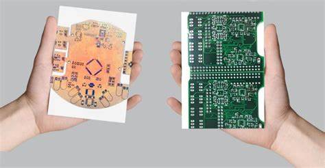
PCB Board Replicating
PCB Board Replicating starts from extract layer drawing of printed circuit board after remove the solder mask layer from it, and then drawing PCB layout accordingly, also the PCB schematic diagram can be restored to improve the electrical performance;
The tool selector buttons reside below the layer controls. They are used to select which layout tool to use in the drawing area. Each tool performs its function when Btn1 is pressed.

Every tool gives the cursor a unique shape that identifies it. The tool selector buttons themselves are icons that illustrate their function. Each layout tool can also be selected from the keyboard:
Escape key Panner tool
F1 key Via tool
F2 key Line tool
F3 key Arc tool
F4 key Text tool
F5 key Rectangle tool
F6 key Polygon tool
F7 key Buffer tool
F8 key Delete tool
F9 key Rotate tool
Insert key Insert-point tool
F10 key Thermal tool
F11 key Arrow tool
Some of the tools are very simple, such as the Via tool. Clicking Btn1 with the Via tool creates a via at the cross hair position. The via will have the diameter and drill sizes that are active, as shown in the status line. The Buffer tool is similar. With it, <Btn1> copies the contents of the active buffer to the layout, but only those parts that reside on visible layers are copied.
The Rotate tool allows you to rotate elements, arcs, and text objects 90 degrees counter-clockwise with each click. Holding the Shift key down changes the Rotate tool to clockwise operation. Anything including groups of objects can be rotated inside a buffer using the rotate buffer menu option.
Pcb board Replicating Line Tool The Line tool is explained in detail in Section 2.5 [Line Objects], page 8. Go read that section if you haven’t already. Activate the Line tool. Set the active layer to the solder layer.
Try drawing some lines. Use the U key to undo some of the lines you just created from Pcb circuit card reverse engineering. Zoom in a bit closer with the Z key. Draw some more lines. Be sure to draw some separate lines by starting a new anchor point with Ctrl-Btn1. Change the ‘crosshair snaps to pin/pads’ behavior in the Settings menu. Now draw a line. Notice that the new line points must now always be on a grid point. It might not be able to reach some pins or pads with this setting.
Increase the active line thickness by pressing the L key. Note that the status line updates to reflect the new active line thickness. Now draw another line. Before completing the next line, make the component layer active by pressing the 4 key. Now finish the line.
Notice that a via was automatically placed where you switched layers. cloning Pcb card does not do any checks to make sure that the via could safely be placed there. Neither does it interfere with your desire to place lines haphazardly. It is up to you to place things properly when doing manual routing with the Line tool after Pcb board Replicating.
Tags: replicate pcb board artwork,replicate pcb board bom,replicate pcb board component list,replicate pcb board design,replicate pcb board diagram,replicate pcb board documents,replicate pcb board drawing,replicate pcb board gerber file,replicate pcb board layout,replicate pcb board part list,replicate pcb board schematic

