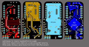
Mixed Signal PCB Reverse Engineering
Mixed Signal PCB Reverse engineering can understand the route and method of current reflow back to ground is the critical point of optimizing the mixed signal PCB reverse engineering. We should not only consider where the current is from, but ignore its route.

Mixed Signal PCB Reverse Engineering for gerber file, layout and schematic
If we must separate the grounding layer when reverse engineering PCB, and must separate the dividing mixed signal line among them, we can separate the single point connection among them first and form the bridge connection among the two grounding. And then reverse engineering the Mixed signal PCB through this bridge. Then each signal track can be provided a direct current reflow back route underneath and force the loop back area small. the process includes:
1> Reverse engineering PCB into separated isolated analog part and digital part, and realize the separation of analog and digital power supply, A/D convertor place on the trans-area;
2> Don’t separate the grounding, but reverse engineering PCB united grounding layer for both analog part and digital part;
3> in all the layers of mixed signal PCB, digital signal can only be reverse engineering in the digital PCB part, while analog signal can only be reverse engineering in the analog PCB part;
4> PCB reverse engineering shouldn’t across the intersection which separate the power supply layer, must go over the mixed signal track which separate the power supply and upon the reverse engineering layer with big area;
5> Analyze the reflow current and the route;
6> Follow the correct and proper mixed signal rules;
Tags: pcb assemble reverse engineering,pcb board reverse engineering,pcb card reverse engineering,pcb reverse engineering,pcba reverse engineering,Printed Circuit Board Reverse Engineering,printed wiring board reverse engineering,pwb reverse engineering,pwba reverse engineering

