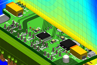
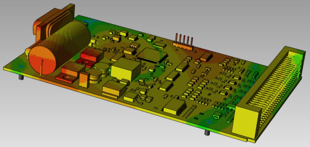
Electronic PCB Board Layout Diagram Design
Electronic PCB Board Layout Diagram Design are by far the most common method of assembling modern electronic circuits. Comprised of a sandwich of one or more insulating layers and one or more copper layers which contain the signal traces and the powers and grounds, the design of the layout diagram of electronic PCB board can be as demanding as the design of the electrical circuit.
Most modern systems consist of multilayer electronic PC boards of anywhere up to eight layers (or sometimes even more). Traditionally, components were mounted on the top layer in holes which extended through all layers. These are referred as through hole components.

More recently, with the near universal adoption of surface mount components, you commonly find components mounted on both the top and the bottom layers. The Electronic PCB Board Layout Diagram Design can be as important as the circuit design to the overall performance of the final system.
We shall discuss in this chapter the partitioning of the circuitry, the problem of interconnecting traces, parasitic components, grounding schemes, and decoupling. All of these are important in the success of a total design.
Printed circuit board effects that are harmful to precision circuit performance include leakage resistances, IR voltage drops in trace foils, vias, and ground planes, the influence of stray capacitance, and dielectric absorption (DA).

In addition, the tendency of PCB board reverse engineering design to absorb atmospheric moisture (hygroscopicity) means that changes in humidity often cause the contributions of some parasitic effects to vary from day to day.

