DC Drive PCB Board Reverse Engineering
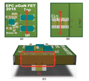
The DC Drive PCB Board Reverse Engineering places the input capacitors and devices on opposite sides of the PCB, with the capacitors generally being located directly underneath the devices to minimize the physical loop size (figure 5).
This layout is considered a vertical power loop because the power loop travels perpendicular to the board plane with vias connecting the power loop through the board. An eGaN FET design arranged in a vertical power loop was created and the part placement and high frequency power loop are shown in below figure with the high frequency loop highlighted in red. Again, space is left between the devices to allow the inductor connection.
For the vertical power loop design, there is no shield layer due to the vertical structure of the power loop. As opposed to the use of a shield plane, the vertical power loop uses a self-cancellation method to reduce inductance. For the DC Drive PCB Board Reverse Engineering, the board thickness is generally much thinner than the horizontal length of the traces on the top and bottom side of the board.
As the thickness of the board decreases, the area of the loop shrinks significantly when compared to the lateral power loop, and the current flowing in opposing directions on the top and bottom layers begins to provide field self-can-cellation, further reducing parasitic inductance.

DC Drive PCB Board Reverse Engineering
In the vertical power loop design, the loop inductance is heavily dependent on the board thickness as the power loop is contained on the top and bottom layers of the PCB. Without the requirement of a shield layer, the distance between the first inner layer and the power loop has little impact on the inductance. To minimize loop inductance in the vertical power loop, the board thickness must be minimized.


