

Clone Transmission control unit PCB board Gerber file
The Transmission Control Unit (TCU) is a vital component in modern automotive systems, responsible for managing the shifting of gears in an automatic transmission. The TCU is built on a PCB board, which integrates complex electronic circuits and components. When the TCU needs repair or customization, cloning the PCB board is often the solution. This process involves replicating the board’s design and functionality by creating an accurate Gerber file.
Features of a TCU PCB Board
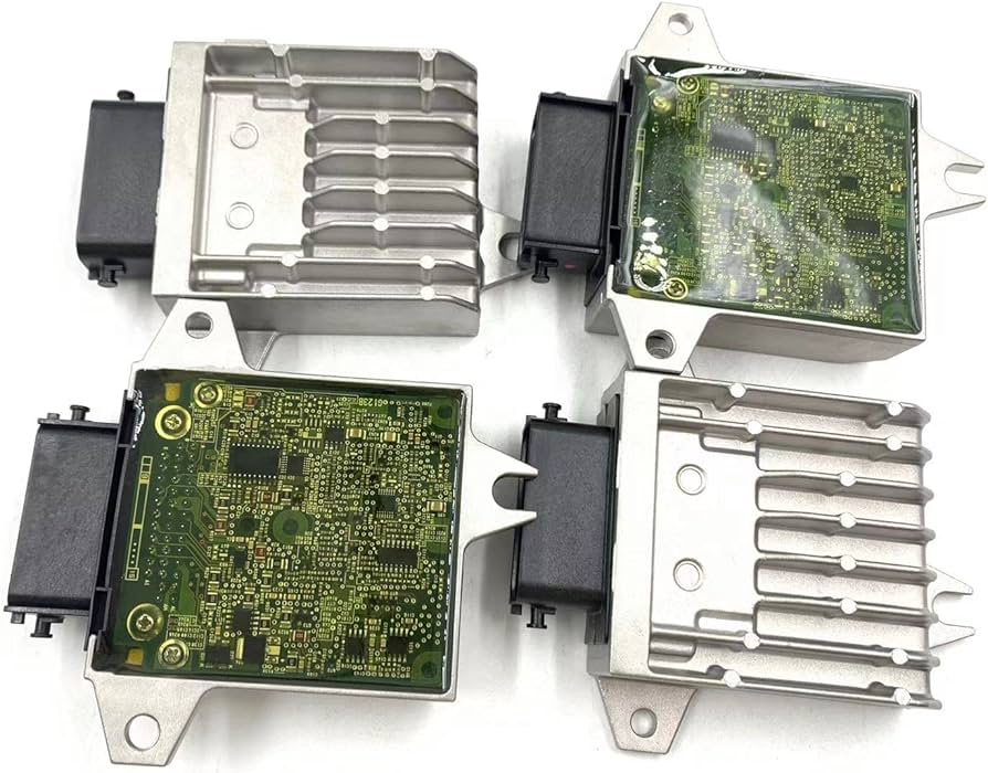
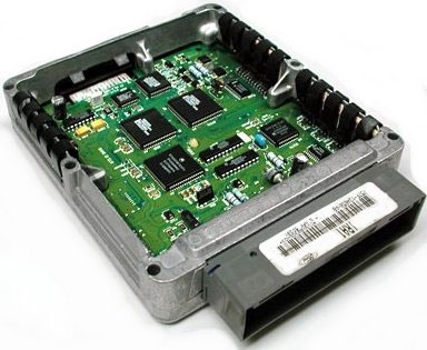
A typical TCU PCB is designed to withstand harsh automotive conditions, including high temperatures, vibrations, and electromagnetic interference. The board features several critical components such as microcontrollers, power transistors, capacitors, inductors, and resistors, all carefully placed on multi-layer PCBs to ensure proper functionality. The PCB layout drawing and the schematic diagram are essential in understanding the relationships between these components.
The Gerber file, which contains detailed information about the PCB layout, provides the necessary data for manufacturing the board, including copper traces, component placements, drill holes, and layers. This file is indispensable for replicating or remanufacturing the TCU PCB.
Challenges in Cloning a TCU PCB
While cloning a Transmission Control Unit PCB board may sound straightforward, several challenges may arise during the process. One of the main difficulties is obtaining a clear and complete schematic diagram or BOM list. Many TCUs are proprietary and come with no publicly available documentation, requiring technicians to rely on reverse engineering techniques.
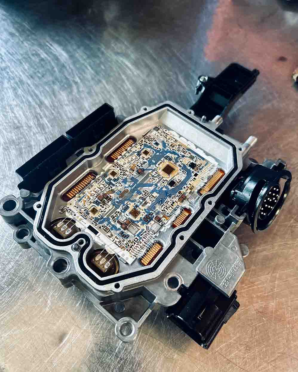
Another challenge is accurately capturing the Gerber file. If the original file is unavailable, the only option is to manually trace the PCB using high-resolution imaging techniques or X-ray inspection. This can be time-consuming and expensive, but it’s essential for ensuring that the cloned board will function exactly like the original.
Additionally, automotive PCBs often include components that are resistant to electromagnetic interference and have specific power management circuits to ensure reliable operation under challenging conditions. When cloning these boards, ensuring the correct component placement is critical. Using the pick & place data correctly is essential to avoid misalignment of components during assembly, which can lead to failure in operation.
The Cloning Process: Step by Step
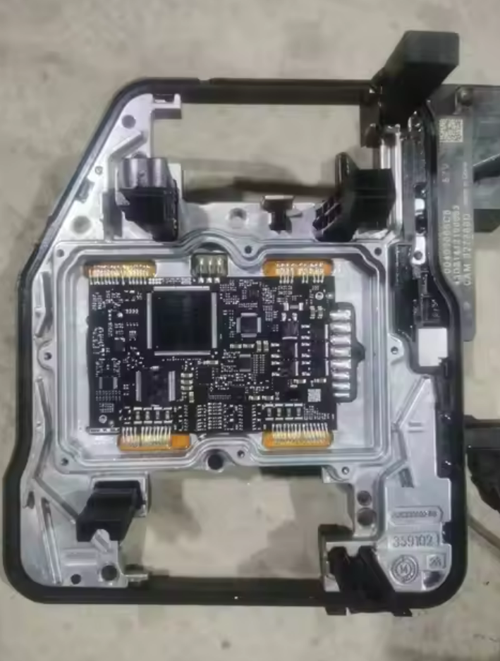
The cloning process typically starts with reverse engineering the original PCB board. This includes capturing the layout drawing, creating the netlist, and ensuring that all components are correctly identified in the BOM list. Once this is done, the Gerber file is generated, which serves as the foundation for producing the new PCB. The CAD file can be used to visualize the design, ensuring that each trace and component is placed precisely.
The pick & place data is then used for component placement during the PCB assembly phase. Once the board is manufactured, a prototype is built and tested to ensure functionality. Testing is essential to ensure that the cloned PCB operates under the same conditions as the original, particularly given the stringent demands of automotive environments.
Conclusion
Cloning a Transmission Control Unit PCB board is a complex process that requires careful attention to detail and a solid understanding of PCB design and reverse engineering. The Gerber file serves as the key document for reproduction, but obtaining accurate schematics and overcoming challenges like proprietary designs and component placement can make the process difficult. With the right tools and techniques, however, it’s possible to restore, modify, or reproduce a TCU PCB that meets the high standards required for reliable automotive performance.