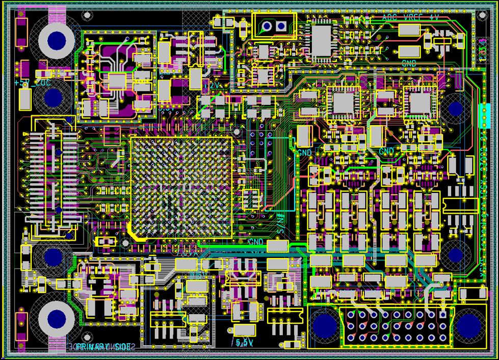
Clone Digital Circuit PCB Board Schematic
When we clone Digital Circuit PCB Board Schematic, the propagation of a digital signal is from one logic gate to another logic gate. The signal is sent from the output end to the receiving end through a wire.

It seems to flow in one direction. Many digital engineers therefore think that the loop path is not related. After all, both the driver and receiver are designated as voltage-mode devices, so why bother to consider current?
In fact, the basic circuit theory tells us that the signal is propagated by current, specifically, the movement of electrons. One of the characteristics of electron flow is that electrons never stay anywhere, and must come back no matter where the current flows.
Therefore, current always flows in the loop, and any signal in the circuit exists in the form of a closed loop. For high-frequency PCB Board signal transmission, it is actually a process of charging the dielectric capacitor sandwiched between the transmission line and the DC layer.

