Circuit Board Wiring Schematic Reverse Engineering
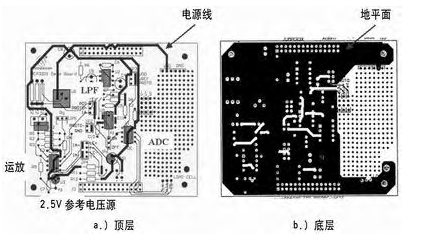
Circuit Board Wiring Schematic Reverse Engineering can improve the conversion result after adding a fourth-order anti-aliasing filter to the circuit. In addition, a ground plane has been added to the circuit board wiring schematic. The wiring shown in below Figure is basically the same, but with a ground plane added to the bottom layer.

The ground plane (Figure 5b) is interrupted by signal lines in several places, so the number of times the ground plane is disconnected should be minimized. The current return path should not be shortened because these traces will limit the current flow from the device to the power connector.

The histogram output by the A/D converter is shown in below Figure. the output codes are much denser. The same active devices were used in both tests. Passive components are different, which will cause small bias differences.


