Reverse Engineering PCB
-
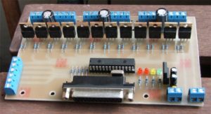
CNC Controller PC Board Cloning
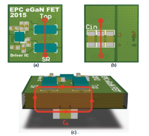
CNC Controller PC Board Cloning To compare the performance of the proposed optimal power loop with conventional lateral and vertical designs from CNC Controller PC Board Cloning for a wide range of applications, four separate board builds were create...
-
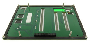
Human Machine Interface Circuit Board Cloning
Human Machine Interface Circuit Board Cloning To enable the high switching speed available from the superior FOM, eGaN FETs were developed in advanced land grid array (LGA) packages that not only have low internal inductance, but enable user to desig...
-
DC Drive PCB Board Reverse Engineering
The DC Drive PCB Board Reverse Engineering places the input capacitors and devices on opposite sides of the PCB, with the capacitors generally being located directly underneath the devices to minimize the physical loop size (figure 5). This layout is...
-
AC Driver Circuit Board Reverse Engineering
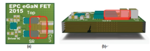
AC Driver Circuit Board Reverse Engineering The first conventional AC Driver Circuit Board Reverse Engineering places the input capacitors and devices on the same side of the PCB in close proximity to minimize the size of the high frequency loop [2]....
-
eGaN FET Effect in PCB Reverse Engineering
eGaN FET Effect in PCB Reverse Engineering With the significant reduction in package parasitics provided by the eGaN FET Effect in PCB Reverse Engineering, the common source inductance is minimized and is no longer the major parasitic loss contributo...
-
eGaN FETs Layout in PCB Duplication
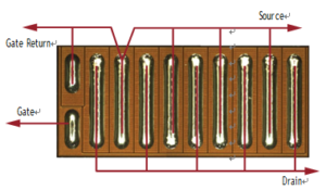
eGaN FETs Layout in PCB Duplication eGaN FETs Layout in PCB Duplication are available in a Wafer Level Chip-Scale Package (WLCSP) with terminals in a Land Grid Array (LGA) format. Some of these devices do not offer a separate gate-return source pin, ...
-
Pulse Width Setting Circuitry on PCB Card Reverse Engineer
Pulse Width Setting Circuitry on PCB Card Reverse Engineer In order to ensure that the pulse signal generated by the projectile passing through the light curtain can be very suitable for the needs of the subsequent processing circuit, in the PCB Card...
-
Shock Wave Resistance Circuit in PCB Board Reverse Engineering
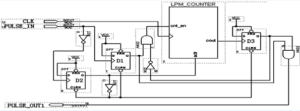
Shock Wave Resistance Circuit in PCB Board Reverse Engineering Filtering the shock wave circuit is shown in below Figure. When a positive transition occurs on the PULSE_IN terminal, the upper edge causes the output of the flip-flop D1 to generate a ...
-
Use FPGA to Filter Wave in PC Board Reverse Engineering
Use FPGA to Filter Wave & Anti-Interference in PC Board Reverse Engineering The main function of Use FPGA to Filter Wave in PC Board Reverse Engineering is to resist shock waves and mosquito interference, and turn the effective projectile signal ...
-
Impact of Stray Inductance on PCB Reverse Engineering
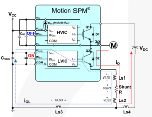
High switching noise may cause a failure in an inverter system. Whenever the IGBT turns on and off, surge voltage is induced due to Stray Inductance on PCB Reverse Engineering of main current paths on the board. below Figures include Ls1 and Ls2, whi...


