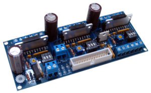
Reverse Engineering PCB
-
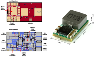
DC Power Converter PCB Board Cloning
DC Power Converter PCB Board Cloning So called analytical placement is an approach widely used in VLSI design, which can also be applied to layout diagram component placement of DC Power Converter PCB Board Cloning. An advantage of analytical placeme...
-
On Board Radar PCB Cloning
On Board Radar PCB Cloning The idea of recursive minimum cut placement is to partition the circuit into subcircuits subject to minimizing the number of wires running between the two partitions of On Board Radar PCB Cloning. Simultaneously, the board ...
-
Reverse Engineering Transmission Sensor PC Board
Reverse Engineering Transmission Sensor PC Board Reverse Engineering Transmission Sensor PC Board will start to a physical sample, before we can fully extract its layout it is necessary to know the way out component routing and placing, methods to es...
-
Antilock Brake Sytem Circuit Card Reverse Engineering
Antilock Brake Sytem Circuit Card Reverse Engineering The task in placement is to position all components on the Antilock Brake Sytem Circuit Card in a way that is feasible with respect to the limitations of the production process. After that all net...
-
ECU Control Module PCB Board Cloning
ECU Control Module PCB Board Cloning The problems faced in the design of ECU Control Module PCB Board Cloning are in many aspects similar to those encountered on PCBs. Again components (cells) are to be placed and have to be connected. Many algorithm...
-
Clone Multilayer Circuit Board
Clone Multilayer Circuit Board Clone Multilayer Circuit Board needs to know how many layers it has, a circuit board is built as a stack of layer pairs. Each pair starts as an insulating sheet with copper deposited on one or both sides. The copper sid...
-
Reverse Engineering Physical Printed Circuit Board
Reverse Engineering Physical Printed Circuit Board Printed circuit board (PCBs), are ubiquituous. PCBs are the backbones of almost every electronic device, and therefore, Reverse Engineering Physical Printed Circuit Board and manufacture it are extre...
-
Industrial Control Circuit Card Assemblies Cloning
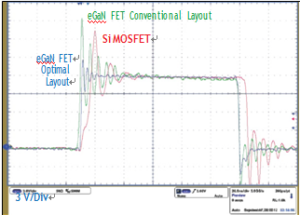
Industrial Control Circuit Card Assemblies Cloning means the layout drawing, gerber file and BOM can be acquired from a physical industrial control circuit card assemblies. With the reduced overshoot and high efficiency achievable with the optimal eG...
-
Reverse Engineering Welder Control PC Board Layout
Reverse Engineering Welder Control PC Board Layout The efficiency results of the three proposed designs from Reverse Engineering Welder Control PC Board Layout compared to a silicon implementation utilizing a vertical power loop with the smallest com...
-
NC Controller Circuit Board Restoration
NC Controller Circuit Board Restoration For the proposed optimal layout, NC Controller Circuit Board Restoration can help engineer to extract the Gerber file, schematic diagram and BOM out from the physical NC controller circuit board sample, the des...


