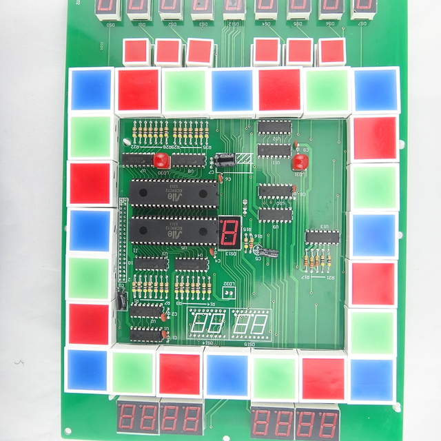
Cassino Multi-Game PCB Board Cloning
Cassino Multi-Game PCB Board Cloning will need to inspect the components placement and positions on the newly created PCB board documents including schematic diagram and layout drawing, netlist and pick & place file;
1. Confirm whether all device packages are consistent with the company’s unified library, and whether the package library has been updated (check the running results with viewlog). If they are inconsistent, be sure to Update Symbols;
2. Confirm the correspondence between the Cassino Multi-Game PCB Board and the daughter board, the jamma arcade pcb board and the backplate pc board copying, confirm that the signals are corresponding, the positions are corresponding, the connector direction and silk-screen identification are correct, and the daughter board has measures to prevent mis-insertion, and the components on the daughter board and the mother board should not interfere.

3. Whether the components are 100% placed;
4. Open the place-bound of the TOP and BOTTOM layers of the Cassino Multi-Game PCB Board and check whether the DRC caused by the overlap is allowed
5. Whether Mark points are sufficient and necessary
6. Heavier components should be placed close to the Cassino Multi-Game PCB Board support point or edge to reduce PCB warpage
7. It is best to lock the devices related to the structure after cloning the circuit board layout is completed to prevent misoperation from moving the position.
8. Within 5mm around the crimp socket, no components with a height exceeding the height of the crimp socket are allowed on the front, and no components or solder joints are allowed on the back
9. Confirm whether the circuit board layout meets the manufacturability requirements (focus on BGA, PLCC, SMD socket)

10. The components of the metal shell, pay special attention not to collide with other components, and leave enough space.
11. The interface-related devices should be placed as close to the interface as possible, and the backplane bus driver should be placed as close to the backplane connector as possible.
12. Whether the CHIP device on the wave soldering surface has been converted into a wave soldering package
13. Whether there are more than 50 manual solder joints
14. When inserting higher components axially on the PCB, horizontal installation should be considered. Leave room for sleeping. And consider the fixing method, such as the fixed pad of the crystal oscillator
15. For devices that need to use heat sinks, confirm that there is sufficient distance from other devices, and pay attention to the height of the main components within the heat sink range

