"Everything we build starts with design engineering. CECL manufactured boards for one of our products. It went perfectly – a real success.It is really an high quality service they have provided to us!"
By Nile Smith from Sinotech Inc.
“We had several very old device with obsolete boards need to be replaced –through CECL professional service.We got what we needed, and we’ve been using the results of the work without any problem till now.”
By Richard Anderson from TWP system Inc.
"Guys from CECL manufacture PCBs we use in one of our products, a clinometer and we’ve never had a problem with anything. The boards come in, they work. And, their team is very responsive."
By Ken Camerlo from Hi-END ADV Inc.
You are here: Home > Reverse Engineering PCB > Reverse Engineering Microprocessor-Backed PCB Board Schematic Diagram on ECU
Reverse Engineering Microprocessor-Backed PCB Board Schematic Diagram on ECU
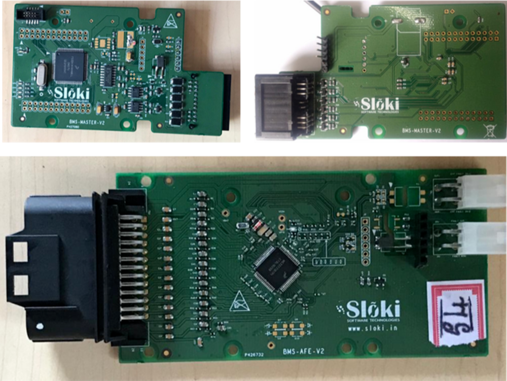
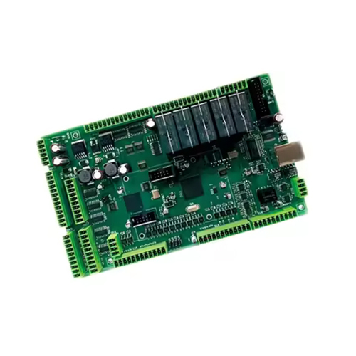
Reverse engineering is a powerful tool for understanding and replicating complex electronic systems. One area where it plays a crucial role is in the recovery and reproduction of microprocessor-backed PCB (Printed Circuit Board) designs, especially for Engine Control Units (ECUs). Engineers often need to reverse engineer a PCB board to obtain a schematic diagram, a critical resource in diagnosing faults, creating prototypes, or modifying existing designs.
La ingeniería inversa es una herramienta poderosa para comprender y replicar sistemas electrónicos complejos. Un área en la que desempeña un papel crucial es en la recuperación y reproducción de diseños de PCB (placas de circuito impreso) respaldados por microprocesadores, especialmente para unidades de control del motor (ECU). Los ingenieros a menudo necesitan aplicar ingeniería inversa a una placa PCB para obtener un diagrama esquemático, un recurso fundamental para diagnosticar fallas, crear prototipos o modificar diseños existentes.
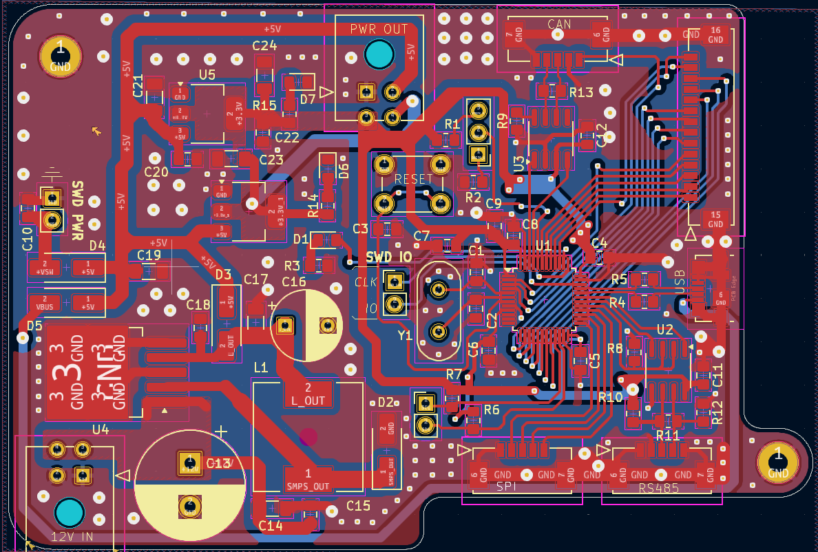
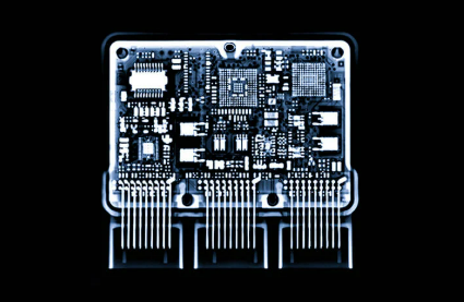
O processo de engenharia reversa do PCB de uma ECU normalmente começa com o exame do layout físico da placa. Usando equipamentos especializados como máquinas de raio X ou dispositivos de escaneamento óptico, os engenheiros extraem dados Gerber ou arquivos que representam o layout exato do PCB. Esses arquivos podem ser cruciais para entender o circuito do projeto, as conexões de pinagem e o posicionamento dos componentes. A próxima etapa envolve interpretar esses dados para criar um diagrama esquemático, que serve como o projeto para o projeto do PCB. Em alguns casos, os engenheiros também podem gerar uma lista de Lista de Materiais (BOM), detalhando todos os componentes usados na placa.
Şematik diyagram kurtarıldıktan sonra, tersine mühendislik süreci orijinal tasarımı değiştirmek veya klonlamak için devam edebilir. Örneğin, mühendisler Gerber dosyalarını kullanarak ECU’nun yeni versiyonlarını prototiplemek veya eski parçaları yeniden üretmek için PCB düzenini çoğaltabilir veya kopyalayabilir. Ek olarak, gelişmiş yazılım araçları, PCB’deki bileşenlerin nasıl etkileşime girdiğine dair daha ayrıntılı bir açıklama sağlayan netlist’i çoğaltmaya yardımcı olabilir. Bu, mühendislerin tasarımı ince ayarlamasına veya daha iyi performans veya verimlilik için optimize etmesine olanak tanır.
By leveraging reverse engineering techniques, companies can breathe new life into older ECUs, recover lost or damaged designs, and develop new solutions to meet evolving technological needs.
Reverse engineering is a powerful tool for understanding and replicating complex electronic systems. One area where it plays a crucial role is in the recovery and reproduction of microprocessor-backed PCB (Printed Circuit Board) designs, especially for Engine Control Units (ECUs). Engineers often need to reverse engineer a PCB board to obtain a schematic diagram, a critical resource in diagnosing faults, creating prototypes, or modifying existing designs.