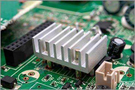
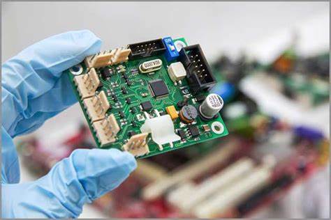
Relayout PCB Board Circuitry Diagram For a better heat dissipation performance
Relayout PCB Board Circuitry Diagram For a better heat dissipation performance over the heat dissipation for electronic components on the PCB board;
a. relocate the heat sensitive components to the cold wind area instead of the place near heat generated source spot.
b. Place the temperature detection PARTs in the hottest position to ensure the temperature situation can be monitored timely.
c. The devices on the same printed circuit board should be redesign as far as possible according to their calorific value and degree of heat dissipation. Devices with low calorific value or poor heat resistance (such as small signal transistors, small-scale integrated circuits, electrolytic capacitors, etc.) should be placed at the uppermost flow (inlet) of the cooling air flow,

Devices with large heat or higher heat resistance (such as power transistors, large-scale integrated circuits, etc.) are placed at the most downstream of the cooling airflow.
d. In the horizontal direction, high-power devices are redesign as close as possible to the edge of the printed circuit board to shorten the heat transfer path;

In the vertical direction, high-power devices are relayouted as close as possible to the top of the printed circuit board to reduce the temperature of other devices when these devices work. Impact.

