Railway Locomotive Recognition and Tracking System PCB Board Reverse Engineering
Railway Locomotive Recognition and Tracking System PCB Board will have chance to use radio frequency technique, so when we Reverse Engineering Railway Locomotive Recognition and Tracking System PCB Board, it is necessary to have a clear mind about the block diagram and its schematic;
Below Figure takes TriQuint’s TGA4506-SM as an example, and shows the circuit board of this amplifier. Note that the input signal is input to the amplifier module through a matched filter network.

The amplifier module generally adopts a common emitter structure of transistors, and its input impedance must match the output impedance of the filter located in front of the low-noise amplifier to ensure the best transmission power and minimum reflection coefficient. For RF circuit board design reverse engineering, this Matching is required.
In addition, the output impedance of the low-noise amplifier must match the input impedance of the mixer at the back end, which can also ensure that the signal output by the amplifier can be input to the mixer completely and without reflection.

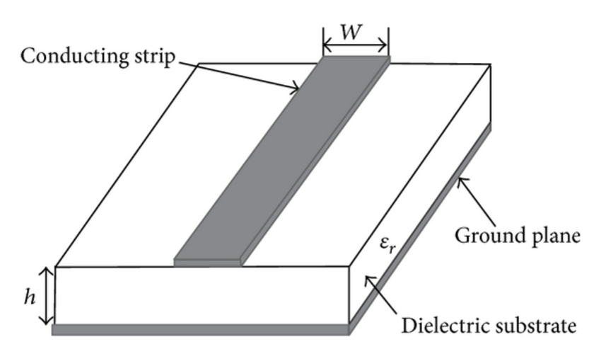
These matching networks are composed of microstrip lines, and in some cases may also be composed of independent passive components, but their electrical characteristics at high frequencies are completely different from those at low frequencies.
It can also be seen from the figure that the microstrip line is actually a copper-clad tape with a certain length and width, and the chip resistors, capacitors and inductors are connected to the microstrip line.

