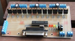
CNC Controller PC Board Cloning
CNC Controller PC Board Cloning
To compare the performance of the proposed optimal power loop with conventional lateral and vertical designs from CNC Controller PC Board Cloning for a wide range of applications, four separate board builds were created. The designs varied the overall thickness of the board and the distance between the top layer and the first inner layer in the board (inner layer distance). The part layouts remained unchanged (shown in figures 4, 5, and 6), and all designs were comprised of four layers with two ounce copper thickness.

CNC Controller PC Board Cloning
The values of the high frequency loop inductance for varying board thicknesses and inner layer distance were simulated and the results are presented in figure 7b. From the data it can be seen that for the lateral power loop the board thickness has little impact on the high frequency loop inductance while the inner layer distance (the distance from the power loop to the shield layer) significantly impacts the inductance.
For the vertical power loop, the inner layer distance has very little impact on the inductance of the design acquired by CNC Controller PC Board Cloning, while the board thickness significantly impacts the inductance by as much as 80% when the board thickness is doubled from 31 to 62 mils.
The interleaved switching node and ground vias are duplicated on the bottom side of the synchronous rectifier. These interleaved vias provide three advantages:
(1) The via set located in between the two eGaN FETs provides a reduced length high frequency loop inductance path leading to lower parasitic inductance.
(2) The via set located beneath the synchronous rectifier eGaN FET provides additional vias for reduced resistance during the synchronous rectifier eGaN FET freewheeling period, reducing conduction losses.
(3) The interleaving of the via sets with current flowing in opposing direction allows for reduced eddy and proximity effects, reducing AC conduction losses.

