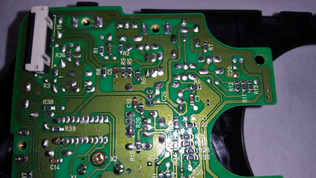
Reverse Engineering Printed Circuit Board Power Supply
Reverse Engineering Printed Circuit Board Power Supply and avoid the inteference among the digital circuitry and analog circuitry;

The selection of reverse engineering Printed circuit board power supply, ground databus layout structure selection——systematic selection: there are a lot of identical or different places in the layout of PCB card cloning of analog circuit and digital circuit.
In the analog circuit, due to the existence of amplifier, the micro-noise generated by the Printed circuit board power supply circuitry will cause the severe distortion on the output signals; however, in the digital circuit, TTL noise’s capacity is around 0.4v to 0.6v, and the limitation of CMOS noise is 0.3 to 0.45 times of Vcc, as a result of that, digital circuit will have a much stronger anti-interference generated from the ground line which can be detected through reverse engineering Printed circuit board probing.
The basic principal requirement:
1, Execute PCB board reverse engineering measure, we should start from the definition of Printed circuit board dimensions, since the dimension of Printed circuit board can be constrained by the external enclosure, and the proper dimension is the perfect fit into the enclosure. Secondly, engineer should consider the connection methods with other external connecting parts such as the potentiometer, socket or other Printed circuit board. and they are normally connected by the plastic wire or metal insulated wire. And sometimes it can also be designed as the socket plug format. Which means, when install a inserted Printed circuit board should spare a contact locations on the device for plug socket.
Tags: reverse engineering circuit board,reverse engineering circuit card,reverse engineering pcb,reverse engineering pcb assemble,reverse engineering pcb board,reverse engineering pcb card,reverse engineering pcba,reverse engineering printed circuit board,reverse engineering printed wiring board,reverse engineering pwb,reverse engineering pwba

