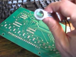
3 Steps of Industrial Circuit Board Repair Process
During industrial circuit board repair process, power supply part should be inspected at the first hand and then come to the other part. +/-5V,
Power supply failure can occur under below several situation:
(1) NO power supply voltage or power supply voltage is deficiency, NC system is often used +/-5V, +/-12V, +/-15V and +/-24V, a few of them use +3.3V, and the varied or unstable voltage of power supply will cause the system working impropery;
(2) Use voltmeter to test the voltage of power supply, and the result show is normal. Voltage waveform detected by oscillograph has shown the existence of big ripple. This situation maybe caused by open circuit of Filtering capacitance, bad rectifier diode or cold soldering, but sometimes it could be caused by an overloaded component which has been brokendown and damaged by power.
(3) System can run properly when it is just being opened, after a while of operating, the voltage begin to drop off. This is usually caused by voltage stabilizing circuit and large power triode.
(4) The voltage decrease accompany with temperature increase maybe cause by component cold soldering, it is electrical connection can be affected negatively when the temperature high up.
(5) NO power supply voltage or supply voltage decreases significantly will cause the system to interrupt or stop working, this fault can be detected and spotted easier.
(6) When the capacity of power supply load drop off or filter circuit become invalid, it will cause the system halt suddenly, this situation which is very difficult to justify can bring damage to the equipment and facility even get personnel wound.
2 Clock Circuit:
Clock circuit mainly exist on the systematic motherboard, it is the foundation of large-scale integrated circuit system through which it can work, it can generate the constant square signal in the circuit base upon the crystal oscillator (commonly known as crystal), Once the crystal oscillator stop working, it is same as the heart of human being stop beating, the whole system will fall into the status of paralyzed, only after crystal can work under normal condition, the systematic circuit can operate under the command of CPU according to the frequency of crystal. The number and frequency of the crystal could be different due to the variety of numerical control system, but generally will at least one crystal, different clock frequencies required by the other circuit can be solved by frequency dividing circuit or other crystal. Crystal possess a higher rate of failure or damage, below are some malfuntions of crystal:
(1) Leakage: Use multimeter and switch to P*10K level to test it, if the resistance is infinite, then it can be viewed as normal;
(2) Internal OPEN CIRCUIT: Value of resistance is infinite tested by Use multimeter, can fail to generate oscillating pulse in the circuit;
(3) Alternative crystal: Due to the transformation of crytal will cause its internal parameter change which can only be detected by osillagraph or cymometer. Although the crystal can still has oscillation, but the clock frequency is deviated from its nominal value, and the still existing oscillation pulse can’t make system circuit work properly due to the value of oscillation is wrong. Only cymometer can test its tolerance now.
(4) In clock circuit, the both ends of crystal would be connected to ground by one ceramic capacitor value range from several picofarads to tens picofarads, failure of the clock circuit result from this capacitor leakage, deterioration is also more common.
The best tool to test whether the crystal is good or bad could be oscillagraph or cymometer, multimeter is very difficult to detect the root cause.
3 Reset Circuit
Reset circuit also exist in the circuit system of motherboard, it is unique set of large-scale digital integrated circuit. Microprocessor and interface circuit are all possess reset terminal. Reset pulse generate by reset circuit will clear the progam counter, force CPU recall the orginal files from the memory, execute initiation process on all the controller chips, system will occurs the phenomenon of disorder or crash as a result of faulty reset circuit, the method of using cymometer to illustrate the reset pulse is turn on/off power supply repeatly, observe and record the pulse value at the right moment of power supply on/off since it should be the normal square wave-form. If there is no existence of reset pulse, all the resistor, capacitor and transistor in the reset circuit should be detected. The reset terminal of integrated circuit should be regular low or high electrical level, or else, it is probably the malfunctional reset circuit or damaged integrated circuit.
Tags: industrial circuit board repair


