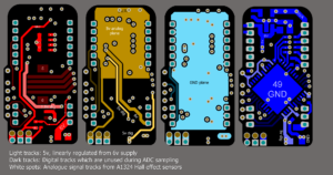
Radio Frequency Circuit of Clone PCB Circuit Card
Designer will encounter Radio Frequency Circuit issue when Clone Pcb circuit card, Radio Frequency Circuit has a lot of special features, and it is very difficult to describe them in a few words, and it is also unable to use the traditional simulation software to analyze such as SPICE.
However, there are some EDA software in the market which has embedded harmonic balance, shooting method and etc complicate algorithm to complete by following PCB reverse engineering rule, it can swiftly and precisely simulate the radio frequency circuits. So before designer start to learn the EDA software, it is critical to understand the radio frequency circuits features, especially some of the dedicated nouns and physical phenomenon since they are all the basic knowledge of radio frequency circuits.
Screen of Radio Frequency Circuits
The concept of wireless transmitter and receiver can be categorize into two parts, base frequency and radio frequency. Basic frequency will include the input signal’s frequency range, as well as the frequency range of output signals from the receiver. The frequency width of the basic frequency determine the basic rate data can flow into the system when Pcb circuit card Clone; basic frequency will be used to optimize the reliability of the data flow, and reduce the transmission medium overload executed by transmitter. As a result of that, when design the basic frequency circuits, need great amount of signal processing knowledge and great amount of experience on printed circuit board reverse engineering ac ground.
The radio frequency circuit from transmitter can convert and upgrade the basic frequency signal into the subscribed channel and at the same time inject the signal into the transmission media. On the contrary, the radio frequency circuit of receiver can obtain the signals from the transmission media when Pcb card Cloning, through conversion and degradation to basic frequency.


