Printed Wiring Board Capacitive Noise & Faraday Shields
Printed Wiring Board Capacitive Noise & Faraday Shields
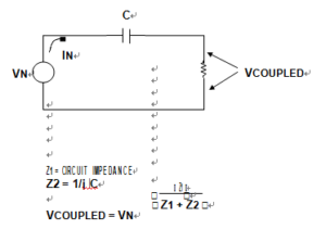
There is a capacitance between any two conductors separated by a dielectric (air or vacuum are dielectrics). If there is a change of voltage on one, there will be a movement of charge on the other. A basic model for this is shown in below Figure.
It is evident that the noise voltage, VCOUPLED appearing across Z1, may be reduced by several means, all of which reduce noise current in Z1. They are reduction of the signal voltage VN, reduction of the frequency involved, reduction of the capacitance, or reduction of Z1 itself. Unfortunately however, often none of these circuit parameters can be freely changed, and an alternate method is needed to minimize the interference.
The best solution towards reducing the noise coupling effect of C is to insert a grounded conductor, also known as a Faraday shield, between the noise source and the affected circuit. This has the desirable effect of reducing Z1 noise current, thus reducing VCOUPLED.
A Faraday shield model is shown by below Figure. In the left picture, the function of the shield is noted by how it effectively divides the coupling capacitance, C. In the right picture the net effect on the coupled voltage across Z1 is shown. Although the noise current IN still flows in the shield, most of it is now diverted away from Z1. As a result,
the coupled noise voltage VCOUPLED across Z1 is reduced.
A Faraday shield is easily implemented and almost always successful. Thus capacitively coupled noise is rarely an intractable problem. However, to be fully effective, a Faraday shield must completely block the electric field between the noise source and the shielded circuit. It must also be connected so that the displacement current returns to its source, without flowing in any part of the circuit where it can introduce conducted noise.


