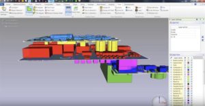
PCB Board Reverse Engineering Topology
PCB Board Reverse Engineering Topology designer can use IP and furthermore, the application of topology plan and layout tools to support the IP, consequently finish the whole PCB Board Reverse Engineering process.
Engineer’s responsibility is through layout as few necessary components as possible, and make critical interconnecting route among these parts to obtain the IP. Once these IP has been obtained, these information will be supplied through PCB clone accuracy designer and they finish the rest of the work.
Nowadays, it is not anymore necessity to acquire the right design purpose through PCB Board Reverse Engineering designer interconnection and mutual communication. Since the designer can have these information in a very precise way, and provide a tremendous help to them. In most of the PCB Board Reverse Engineering process, schematic designer and PCB Board engineer must execute interconnect layout and arrangement, which will consume great amount of both side’s precious time.
From the previous experience we can see the interconnect operation is very necessary but too much time consuming and the efficiency is very low. The preliminary plan provided by the designer could probably be a hand craft drawing, without any proper components with right proportion, bus line width or pin output tips.
Accompany with introduction of the PCB Board Reverse Engineering designer, although the application of topology technique can acquire some of the components layout and interconnection. This design will probably require to layout more components, acquire other INPUT/OUTPUT and other databus structure and all interconnection to achieve the task.
PCB Board Reverse Engineering designer need to use topology plan, through the interaction of components on the already finished layout and semi-finished layout to achieve the best layout and interconnection, as a result of that, to improve the PCB Board Reverse Engineering efficiency.


