Inverter PCB Board Gerber File Reverse Engineering
For all these Inverter PCB Board Gerber File Reverse Engineering, the power strategy should be to connect all ground, positive and negative power pins to the analog plane when design analog and digital circuitry.

Moreover, the ‘COM’ pin or ‘IN’ pin related to the input signal should be connected as close as possible to the signal ground.
For higher resolution successive-approximation A/D converters pcb wiring diagram reverse engineering (16-bit and 18-bit converters), a little extra care is required when isolating digital noise from the “quiet” analog converter and power plane.
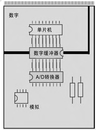
When these devices are interfaced with a microcontroller, an external digital buffer should be used to obtain noise-free operation. Although these types of Inverter PCB Board usually have internal double buffers on the digital output side, external buffers must be used to further isolate the analog circuits in the inverter from digital bus noise.
The correct power strategy for this system is shown in below Figure.

Above Figure. For high-resolution successive approximation A/D converters, the power and ground of the converter should be connected to the analog plane. Then, the digital output of the A/D converter should be buffered using an external three-state output buffer. In addition to the high drive capability, these buffers also have the function of isolating the analog and digital sides

