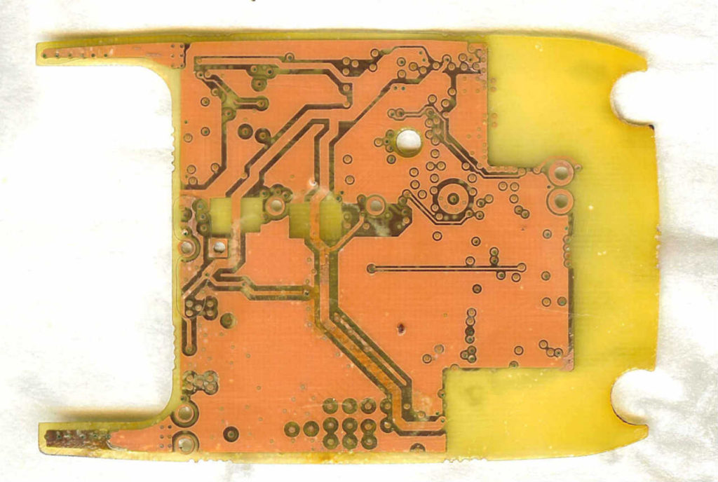
Cloning Printed Circuit Card Position
When Cloning Printed Circuit Card, the input-field pops up (temporarily replacing the status-line) whenever user input is required. Two keys are bound to the input field: the Escape key aborts the input, Return accepts it. Let’s change the name of a component on the BOM list which has been extracted from master PCB board to see how the input-field Works. Position the cross hair over R5, and press the N key. The input field pops-up showing the name for you to edit.

Go ahead and change the name, then hit return. Notice the name of the element changed. Now undo the change by pressing the U key. You can position the cross hair over the name, or the element before pressing the N key.
Now select ‘realign grid’ from the Screen menu. Notice that the status line has been replaced with an instruction to position the cursor where you want a grid point to fall after Printed circuit card replicating. In this case, since the cross hair can only fall on a grid point, you must move the tip of the finger cursor to the place where you want a grid point to appear.
Don’t worry that the cross hair is not coincident with the cursor. Click Btn1 at your chosen location. See how the grid has shifted, and the status line has returned.
The present cross hair position is displayed in the upper right corner of the window. Normally this position is an absolute coordinate, but you can anchor a marker at the cross hair location by pressing Ctrl-M (try it now) and then the display will read both the absolute cross hair position as well as the difference between it and the marker.
The numbers enclosed in < > are the X and Y distances between the cross hair and the mark, while the numbers enclosed in parenthesis are the distance and angle from the mark to the cross hair. The values displayed are always in units of 0.001 inch (1 mil). Pressing Ctrl-M again turns the marker off.

